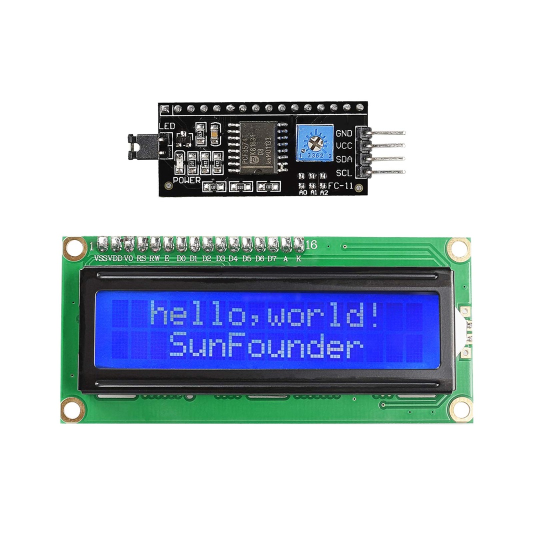
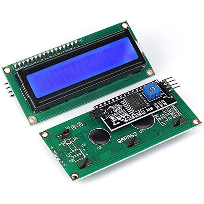
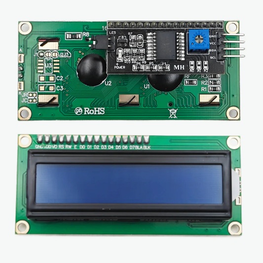
LCD 16×02 Display Interface
Key Components & Pinout (Standard Parallel)
- Pins: Usually 16 pins (VSS, VDD, V0, RS, RW, E, D0-D7, A, K).
- Contrast (V0): A potentiometer adjusts contrast; often connected to VSS/VDD.
- Backlight (A/K): LED+ (Anode) and LED- (Cathode) for illumination.
- Control: RS (Register Select), R/W (Read/Write), E (Enable).
- Data: D0-D7 for 8-bit mode, D4-D7 for 4-bit mode.
Interface Modes
- 8-bit Mode: Uses all 8 data lines (D0-D7) for fast, direct data transfer but consumes more pins.
- 4-bit Mode: Uses only 4 data lines (D4-D7) by sending data in nibbles (half-bytes), saving MCU pins.
- I2C/SPI Adapter: A small module converts the parallel interface to 2 (SDA, SCL) or 4 wires (MOSI, MISO, SCLK, CS), drastically reducing pin usage and simplifying wiring.
Common Uses & Setup
- Microcontrollers: Easily interfaced with Arduino, ESP32, STM32 via libraries (e.g., LiquidCrystal).
- Function: Displays real-time status, sensor readings, or messages in DIY electronics projects.
- Setup: Requires connecting power, ground, contrast pot, and data/control lines to the MCU, then using specific library functions to send text and commands.