IC BASES
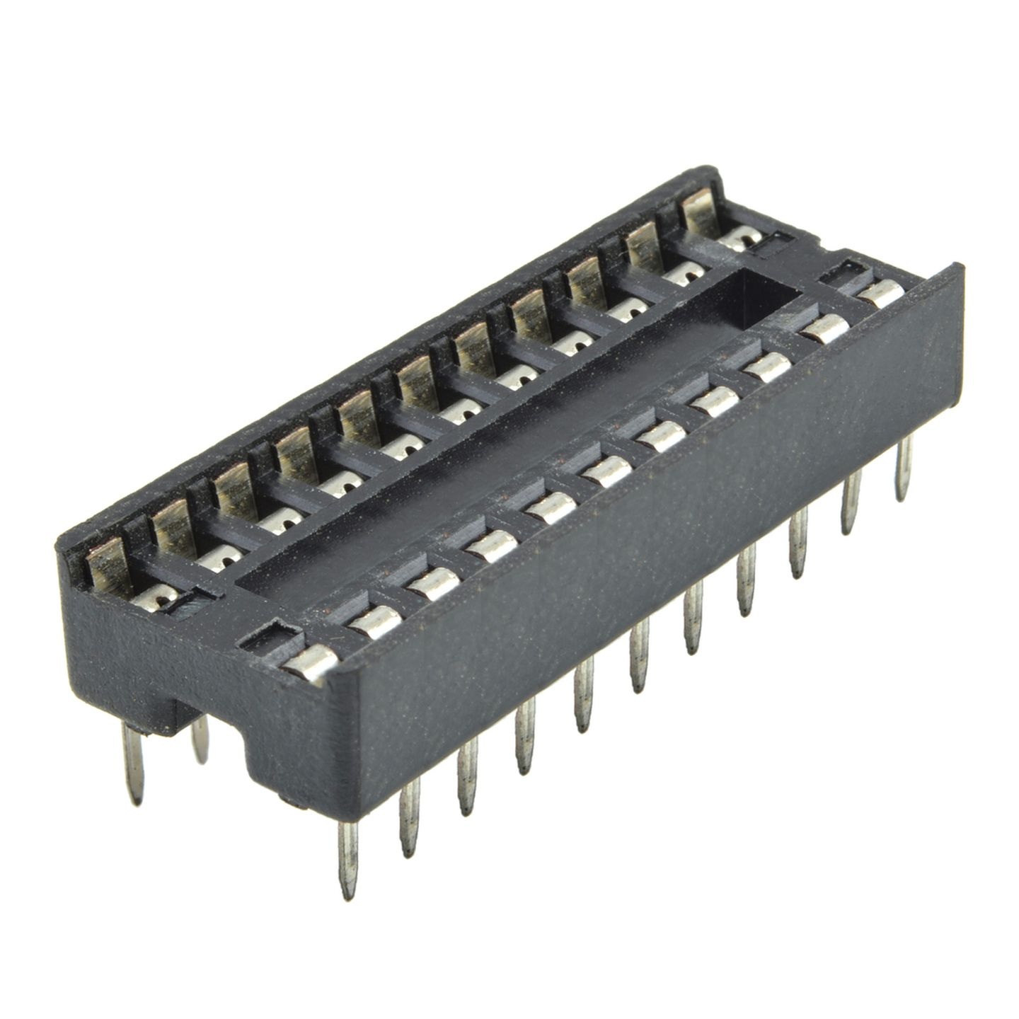
IC Bases, also commonly known as IC Sockets, are electromechanical devices used to connect Integrated Circuits (ICs) to a printed circuit board (PCB) without permanent soldering. They provide a “plug-and-play” interface, allowing the chip to be easily inserted, removed, or replaced. This is essential for protecting expensive or sensitive chips from the heat of a soldering iron and for simplifying future repairs or upgrades.
Specifications
IC bases are selected based on their contact reliability and mechanical design:
- Contact Types:
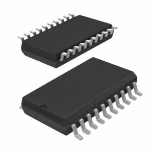
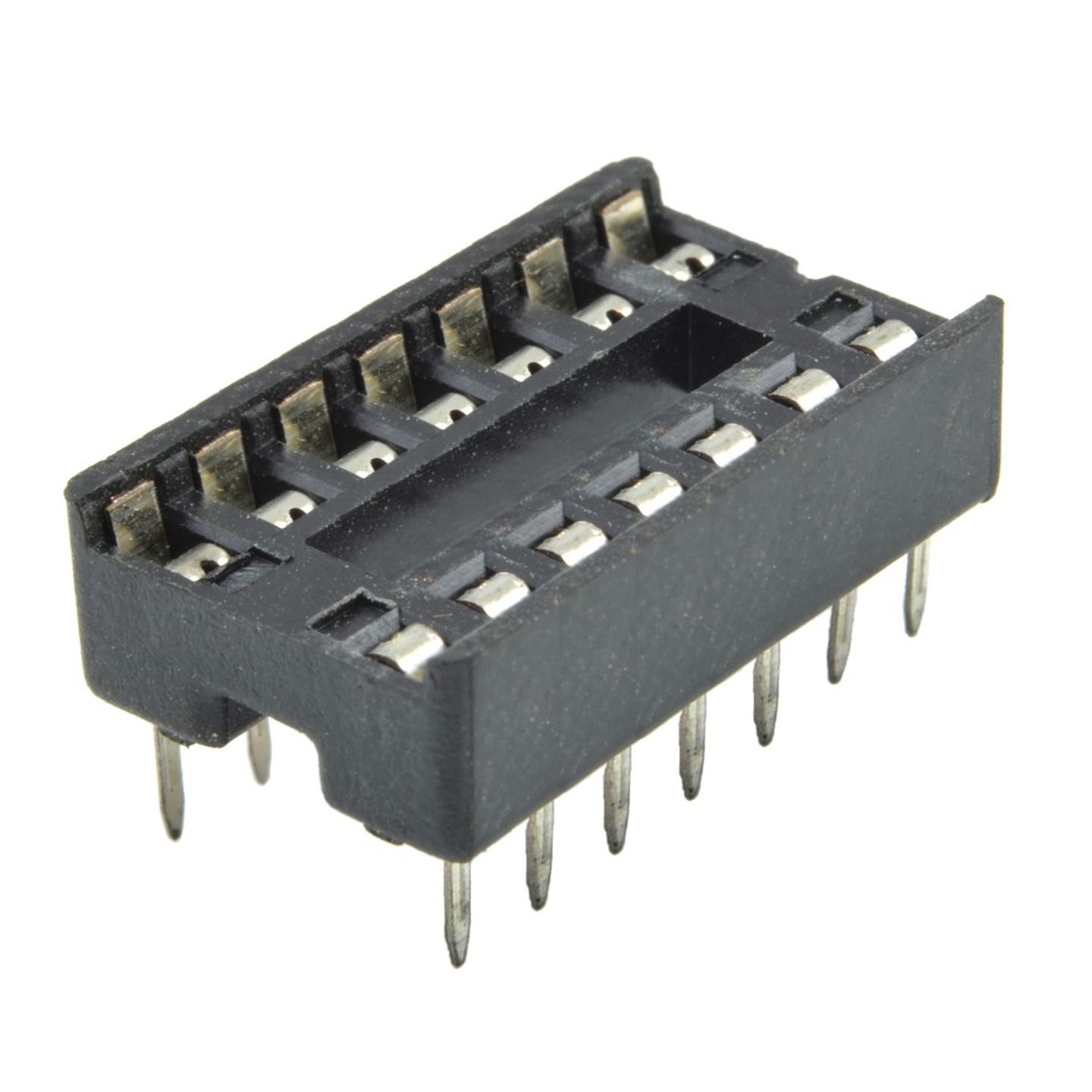
- Flat/Dual-Leaf Pins: Economical and common; uses flat spring metal to grip the IC legs.
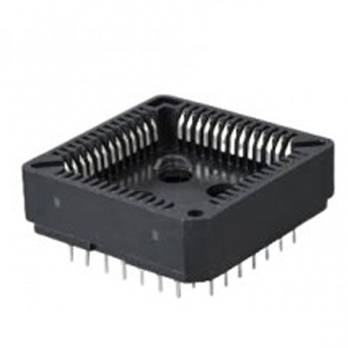
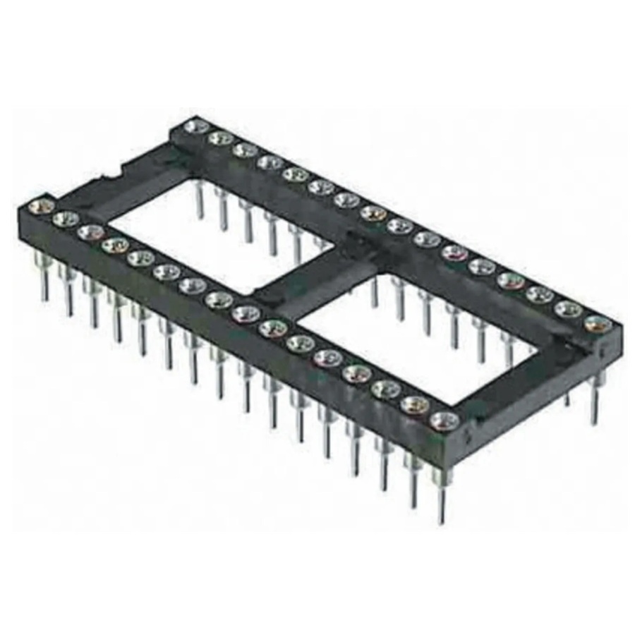
- Machined/Round Pins: High-reliability pins with gold-plated internal clips for superior electrical contact and vibration resistance.
- Pitch (Spacing): Standard 2.54mm (0.1″) for most through-hole projects; specialized pitches for high-density SMD testing.
- Material: Typically made from PBT (Polybutylene Terephthalate) or high-temp Nylon, with tin or gold-plated copper alloy contacts.
- Current Rating: Usually rated for 1A to 3A per contact.
- Temperature Range: Industrial-grade bases can operate from -55°C to +125°C.
- Insertion Force: Available in standard or Zero Insertion Force (ZIF) styles, the latter using a lever to lock the chip in place without friction.
Available Sizes
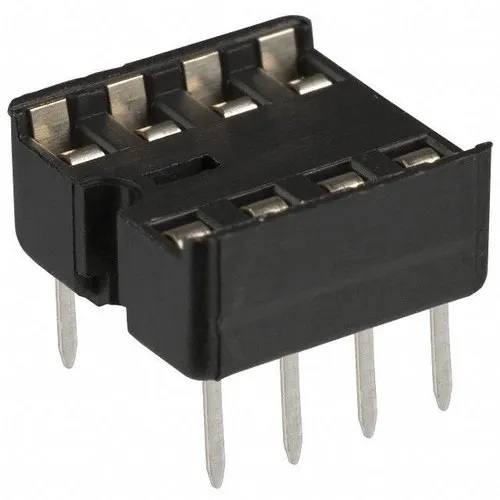
IC bases are sized by their pin count and the width between the rows of pins:
| Pin Count | Row Width | Common ICs Used |
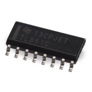
| 8-Pin | 7.62mm (0.3″) | Op-amps (LM358), Timers (555), small EEPROMs. |
| 14 / 16-Pin | 7.62mm (0.3″) | Logic gates (74-series), Shift registers. |
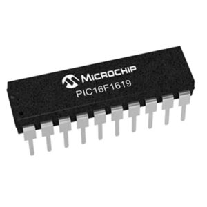
| 28-Pin (Narrow) | 7.62mm (0.3″) | Narrow-body Microcontrollers. |
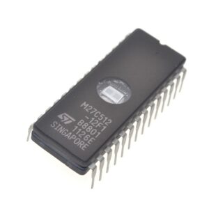
| 28-Pin (Wide) | 15.24mm (0.6″) | Larger Memory chips, EPROMs, ATmega328P. |
| 40-Pin | 15.24mm (0.6″) | High-pin-count Microcontrollers (8051, PIC16). |